So, how does routing work, anyway? (Part 1)
It’s a question that I get from time to time and it’s time to answer here. If you understand the fundamental principles of networking, then all the other parts of building and maintaining an ISP network (wired OR wireless) are much simpler. In this series of articles we will discuss the processes that make IP networking function by delving into the fundamentals of how subnetting works, how a router USES subnet information and the very important arp process.
This topic is an easy topic to understand, but it is difficult to organize the materials and ideas needed to easily explain. This is because there are so many pieces that are related and understanding one part is necessary to understand the next. You, as a reader, may need to read this article more than once in order to fully understand all of the parts. We will use the following “talking points” to cover this topic:
- Networking basics – what is needed to make two or more computers communicate?
- What is a router and why is it a necessary component in a network?
- Subnet masks and what they mean. What, exactly, IS a subnet address and why do I care?
- ARP – what is it and what does it do?
- Wrap up and tying up the loose ends.
It may seem self evident to us, but some things just need to be defined. In order for you to understand the patterns of symbols that you see on this page, there has to be a common platform that we use as part of the communication process. I am writing using the English language, which has 26 “letters” defined and we can use our common understanding that when these 26 letters are combined in certain orders, they form words.  In order for communication to occur, it must be assumed that when I use a particular word, the meaning I am attempting to convey is the same meaning you derive as a reader. We use a dictionary to define what each word means.
When computers need to communicate with one another, they must, also, use a common language. When we talk about this “language” as it relates to computer communication, we call it a protocol. Generally speaking, when two or more computers begin communicating, there is often more than one protocol in use. Let’s use an example communication to explain. For our example, we have one computer (call it the “client”) needs to create a telnet session to another computer (call it the “server”). Let’s further assume that both computers are connected to each other through an Ethernet switch. For this example, we know that the session will use “telnet”, which has a strict set of communication parameters, or protocol. The communication happens via a set of protocols called TCP/IP. TCP, or “transmission control protocol”, has specific parameters and behaviours defined, as does IP, or “Internet protocol”. In order to pass the data from the client to the server (and back again), we will have to use still another protocol on the Ethernet switch. As you can see, it is no trivial thing to get all these components working together.
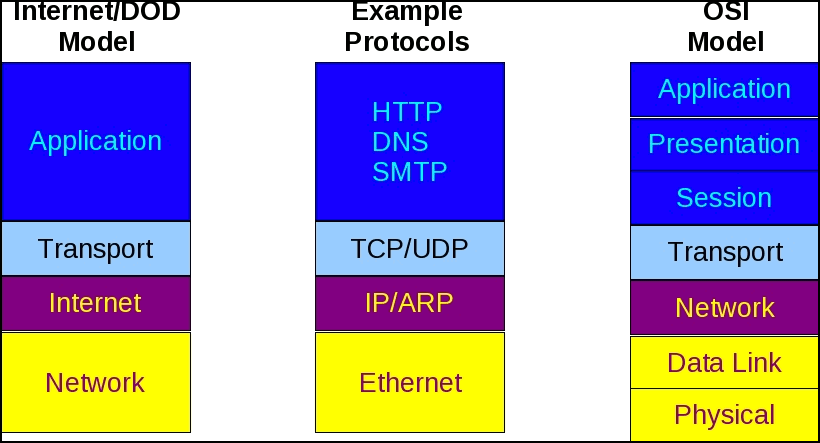
At this point, I will introduce something called the OSI (Open System Interconnection) model. The OSI model is a model that describes some of the parts that are needed in order to allow communications between devices on a network. It is important to distinguish between the OSI model and a protocol definition. The OSI model does NOT describe a particular protocol (or set of protocols). It simply describes, in generic terms, the processes that happen in order for communication to happen.
The OSI model is usually shown as 7 distinct layers. I’m not going to describe the function of each layer, because that information is readily available. You can see a detailed description here: http://en.wikipedia.org/wiki/OSI_model. For the purpose of this tutorial, I simply wanted to present an image so that when we discuss these layers later, you’ll have something to refer to. In the image below, you see both the OSI reference model AND the Internet/DOD model (which is the protocol model upon which TCP/IP is built).
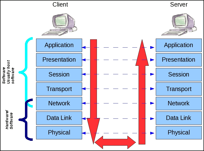
“So, what?”, you may be saying. Let’s take a look at how the OSI model applies to us. Consider the image below.

Let’s assume that you (“Client”) want to send an email. The “Server” machine would have been configured in your email software on the client side. When you finish typing the email and click “Send”, the application hands the email data over to what is referred to as the “IP Stack”. The operating system you have running on your computer includes the parts needed to implement the communications via TCP/IP. The portion of the operating system that allows for direct communication with your email application handles the “Application layer” function of the OSI model. Notice the red arrows in the image. These arrows indicate that the email you sent gets handed to the different parts of the operating system, in order, as it passes down the stack. At various points in the processing of your email communication, the data is formatted into a packet is physically sent out an interface on your computer. Ultimately, this packet, which includes your email, is picked up by the server’s network interface. At this point, it is at the bottom (Physical layer) of the server’s IP stack. This email is passed UP the server’s IP stack and the bits that were added by your IP stack are stripped off, eventually arriving at the server’s mail server application with the email you typed.
You’ll notice that the various layers have arrows going across the image pointing between the layers of the client and server machines. This “ladder” is there to show you that the bits of information added in the client’s IP stack at, for example, the Network layer are used to communicate something to the Network layer at the server. In the case of TCP/IP, the Network layer is responsible for adding the IP header to the data packet. This is what allows the server to know how to reply to the client, because the source IP address in the IP header is the IP address of the client.
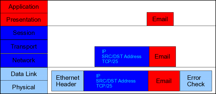
Consider the following image.

As the email passes down throught the IP stack, you see that the system adds the IP header, which inlcudes information such as source and destination IP addresses. Also, at the session layer, the TCP header is added, which includes information such as the source and destination ports. We’ll discuss the information found the these headers in later articles in this series. Finally, as the email passes down to the bottom part of the IP stack, you see that the physical transport header (in this case, it’s an ethernet network) is added. The bottom picture is the information that is physically pushed out the interface. When it arrives at the server side, the ethernet header may not be the same, if the server is on a physically different network, but the IP header and email data will go unchanged all the way to the server. There is an exception to this, but that, too, will be part of another article in this series.
In this article, I have covered some of the details of the OSI reference model and how it is implemented in the TCP/IP suite of protocols. In the upcoming articles in this series, we will discuss the function of a router and how our computers see the network. We will, also, discuss the idea of subnetting and how it affects our computer’s communication with other devices on the network. For now, I hope this article has given you some insight on how computers communicate.

June 9th, 2013 at 3:12 pm
[…] Contenido original … […]